Editor
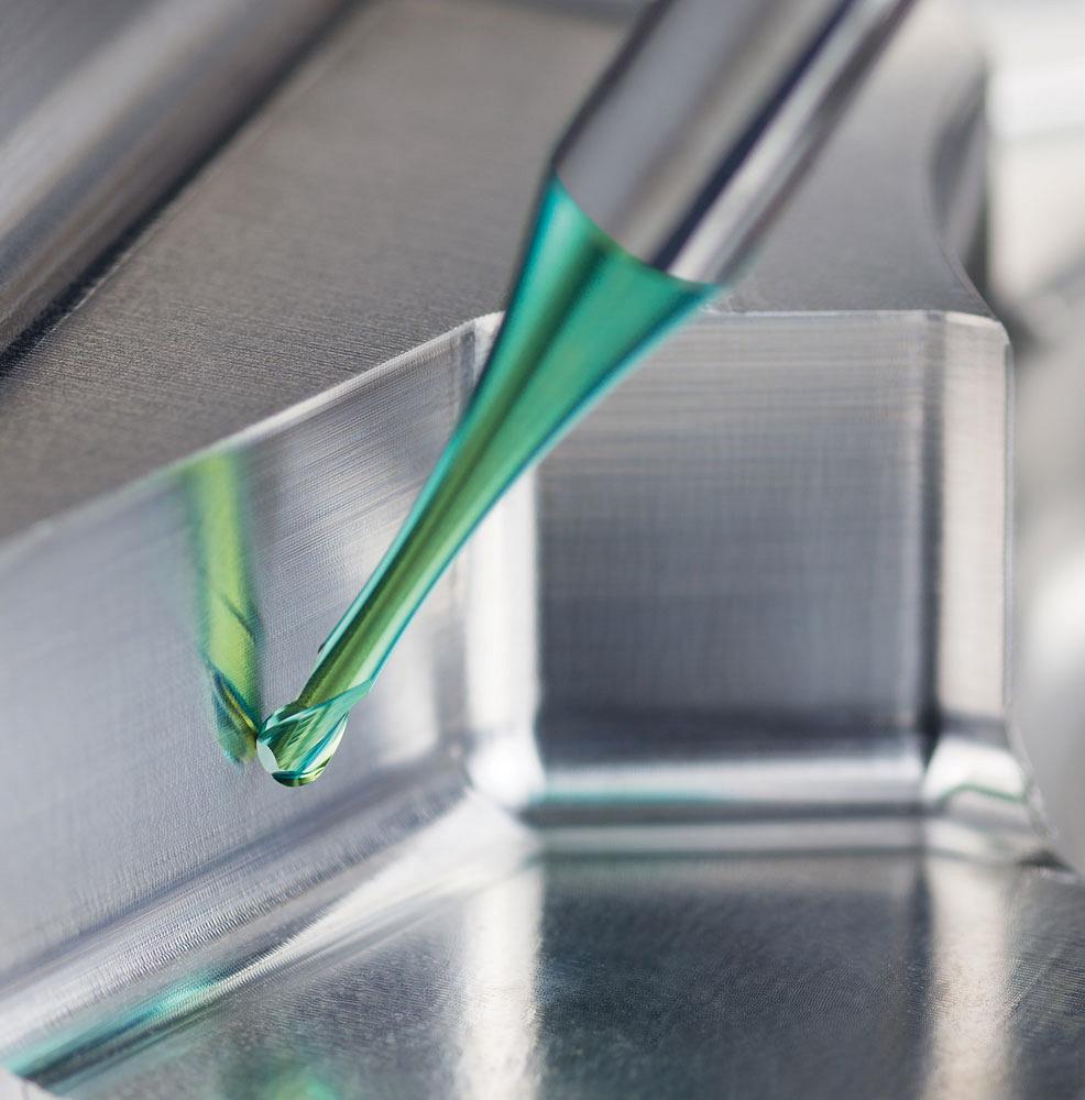
Care should be taken when choosing speeds, feeds, DOC in micromilling applications. Even the smallest mistake can break these small tools. Photo courtesy of Emuge Corp.
Micro end mills are small. Really small.
While no hard-and-fast definition exists to describe the size of these tools, a maximum diameter of around 2 to 3 mm is a good guideline. Quite often they are much smaller.
At this small scale, even the slightest incorrect tool movement, feed rate input, or depth-of-cut (DOC) selection can have disastrous results. The surface finish of a part or part feature easily is ruined, tools will wear prematurely or even break, and parts become scrap with just a single small error being made.
At such a small scale, every decision is big.
This type of tool commonly is used by manufacturers of parts in the medical, aerospace, and telecom sectors, and even in micro mouldmaking. Whether machining small part features or manufacturing small parts, required accuracies of 0.00254 mm are not uncommon.
Like any machining operation, tool selection for micromilling starts with the workpiece material. The part’s material, particularly its hardness, helps machinists choose the correct tool for the job.
“Material hardness plays a role in tool selection, even when it comes to microtools,” explained John Kollenbroich, head of product management, Horn USA, Franklin, Tenn. “Very soft materials can easily load up flutes. Harder materials do not present the same chip loading issues, because you are usually taking smaller ap [axial DOC] and ae [radial DOC] values, but the material hardness itself is challenging.”
A good rule of thumb is that if the material hardness is 55 HRC and under, use carbide tools. If it’s above 55 HRC, use cubic born nitride- (CBN-) tipped tools. The material’s makeup, in particular how well it shears, also affects tool choice.
This shearing effect is important when surface finish requirements (Ra) are critical.
“Surface finish in aluminum applications is an area where solid carbide may not be the best option,” said Kollenbroich. “When trying to maintain finishes below 10 Ra, you need to look at diamond-tipped end mills designed specifically for achieving excellent surface finishes, usually in the 4-Ra and lower range.”
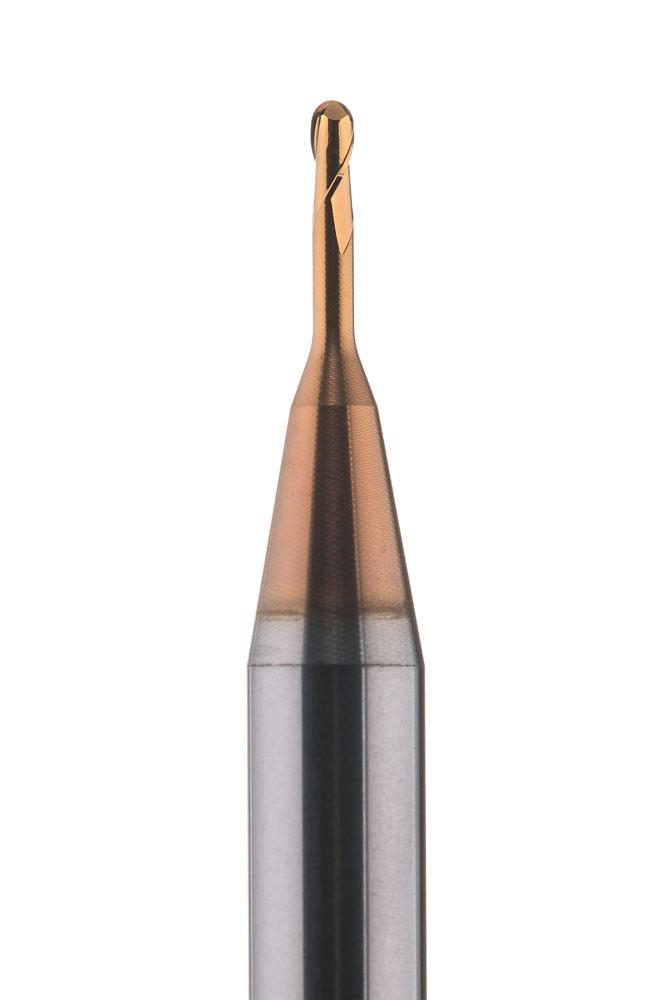
The DS Micro Torus end mill has a 1 mm dia. and is used for profiling and contouring heat-treated materials. Photo courtesy of Horn USA.
Workpiece material also factors into the process of selecting the cutting data that should be used. Some materials require a greater chip load to help prevent work-hardening, while other materials need much lighter ae and ap values to be used because of the material’s hardness.
Once you have selected your material type, you can now focus on the application, and it should be pointed out that side milling, face milling, and profile milling all require different machining parameters.
According to Kollenbroich, consistent and constant chip load is necessary for some applications, like profiling milling. For other applications, such as trochoidal milling, it is not regularly applied and is only possible using CAM software.
“Using constant and consistent chip load makes wear and tool deflection much more predictable,” said Kollenbroich. “It allows better finishes to be produced because you will see similar results across the entire surface. Tolerances usually can be held better, and tool life becomes more easily monitored.”
The process of maintaining consistent and constant chip load typically is done by the CAM system. These systems use the remaining stock left after the roughing stage and work accordingly. A part may need to be broken down into different segments, with different machining strategies being applied, to be completed with the right accuracy and surface finish.
“When manufacturing small parts with micro-style end mills, a strict disciplined cutting strategy is very important to the longevity of the tool. Stock awareness of the previous roughing or semi-roughing process needs to be considered prior to completing the finishing process. Any areas with stock that may exceed the final finish pass depth of cut could cause tool breakage,” said Dan Doiron, product manager – milling, Emuge Corp., West Boylston, Mass.
Cutting data also is affected by the tool’s type and size. Smaller tools cannot handle the same ae and ap values that a larger tool can.
“Each tooling manufacturer has its own published operating ranges. These should be closely followed, because the tool originally was designed to work within those ranges. Running below the recommend vales could cause rubbing and decreased tool life, whereas overstepping those values could result in breakage,” said Kollenbroich.
Chip formation in micromilling is critical, and it is also material-specific. Each material requires its own methodology to form a chip properly. This is where proper tool selection is crucial. The tool’s substrate, coating, geometry, and cooling ability all must be considered to not only form a proper chip, but also remove it from the work zone.
“With microtools, the recutting of chips can be catastrophic because these small-diameter tools cannot handle that type of load,” said Kollenbroich. “A chip that gets between your cutting edge and the workpiece does not cut but slides along and deflects your tool. At a certain point, either the tool breaks or the chip gets cut, putting an excessive load on the tool. Special care needs to be observed when evacuating chips with microtools.”
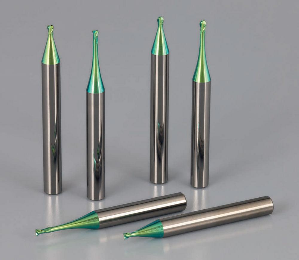
Whether machining small part features or manufacturing small parts, required accuracies of 0.00254 mm are not uncommon. Photo courtesy of Emuge Corp.
The smaller the tool diameter, the more important its chip formation and evacuation become. Having safe, efficient chip evacuation helps create a reliable cutting process.
“Packing chips, especially in confined areas such as in a mould cavity or the machining of a rib feature, will cause the recutting of chips and will rapidly fracture the cutting edge of the end mill,” said Doiron.
The number of flutes also plays a big role in chip evacuation. If the tool has too many flutes, it creates excessive load from having too many teeth in the cut simultaneously. If there are too few flutes, cycle time typically is increased. The number of flutes also is application-specific.
“If you are milling a side wall, trying to achieve a good finish and flatness, then you would want a tool with a high number of flutes, even five or more,” said Kollenbroich. “If you are slotting, however, then too many flutes could be a problem, so you would most likely use a two- or three-fluted tool. In profiling milling, your limitation is usually based on centre-cutting, full-radius end mills, which typically are two-fluted tools.”
There are times when an odd number of flutes also is beneficial because it reduces harmonic vibration. Another answer to this problem is using tools with a variable helix and pitch.
“These determinations also become material-specific so, again, selecting the proper tool for the application is important,” said Kollenbroich.
The rake angle also influences chip formation. According to Kollenbroich, some materials require a chip to be peeled off, where others need the chip to be pushed off. Every application is different, and using a tool that has been designed for each application is a necessity, especially when dealing with microtools.
The rake of the tool depends mainly on what material the tool is designed to machine. End mills designed specifically for machining hardened materials will normally be negative on larger-diameter tools and neutral on smaller-diameter and microtools. A tool designed for machining titanium or aluminum has a more positive rake angle to allow for a free-cutting application and proper chip production.
The application of coolant in micromilling is a tricky proposition at best. A modern cooling strategy normally involves the use of high-pressure coolant; however, it’s usually not used in small-tool applications because the pressure of the coolant alone is enough to break the tool. In these operations, air or an air/oil mist is used. Another option is to use an external coolant line directed at the tool.
“Regardless of the method used, it is critical to get these chips away from the work zone,” said Kollenbroich.
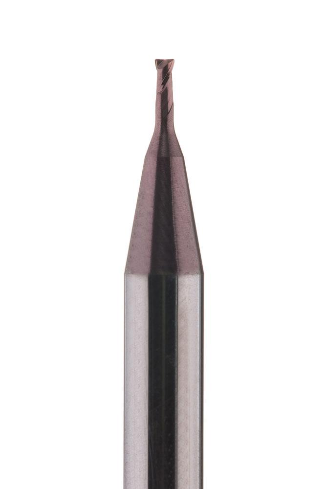
This DS Micro ball-nose end mill has a 1 mm dia. and is used for cutting high-strength materials. Photo courtesy of Horn USA.
A coating offers two main advantages: hardness and lubricity. It also can extend tool life in most operations. In short, coatings are key to the tool’s longevity and overall performance.
Lubricity and hardness both come from the nature of the coating material that is being applied. Both are important. Common coatings include titanium nitride (TiN), titanium carbo nitride (TiCN), titanium aluminum nitride (TiAlN), aluminum titanium nitride (AlTiN), and aluminum chromium nitride (AlCrN).
“The type of coating depends on the application,” said Doiron. “A smooth and defect-free coating is always important. Another important strategy is to apply a constant coating thickness for sharp cutting edges. The coating might appear to be a colour that was added to the tool to be visually appealing, but the coating is critical to the tool’s performance and will react when the cutting action starts and as the heat generation on the cutting edges starts to occur. Historically, cutting tools were originally created without coating, but the tools evolved to include this vital protection.”
Other benefits of using a coated tool are:
“Having a slick surface, or better surface lubricity, allows the chip to slide off more freely and aids in reducing heat,” said Kollenbroich. “Hardness, on the other hand, is somewhat tied to the machine’s ability to run enough speed to get the coating into the oxidation stage. Once certain coatings get hot enough, an aluminum oxide layer can form between the tool and the chip. This layer helps transfer heat away from the tool and into the chip.”
However, on small-diameter tools, achieving high enough speeds to reach the oxidation stage may not be possible because of spindle limitations.
Uncoated tools typically wear faster and can suffer from built-up edge (BUE). These wear modalities sometimes can be overcome by modifying the speeds, feeds, and ae and ap and by advanced programming strategies.
“Running a coated tool usually is your best option. Even if you cannot reach the necessary speeds, you may still gain additional tool life from the base surface hardness offered by the coating,” said Kollenbroich.
Coatings are difficult to apply to tiny tools. The necessary edge prep required for any coating makes the tool too dull at such small diameters. This means that the coating would have to be applied in a very thin layer with no edge preps.
“There are few coating processes that can achieve this requirement,” said Kollenbroich. “One that comes to mind is the high-power impulse magnetron sputtering (HiPIMS) process. This is a process that Horn offers on many of its tools. This coating process can be applied with little to no edge prep while maintaining very low compressive stresses. Although most microtools are supplied with no coatings, it is possible to offer microtools as a coated option, and we do offer this for tools down to 0.1 mm diameter.”
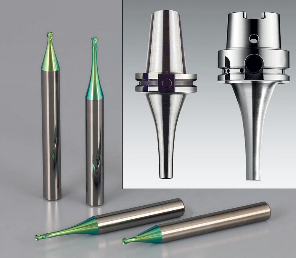
Toolholders play a critical part in micromilling tool performance and is one area often overlooked by many manufacturers. Photo courtesy of Emuge Corp.
According to Doiron, Emuge uses the physical vapour deposition (PVD) process for the coating on its micro end mills.
The root cause of deflection in micromachining is tied to improper cutting parameters. Incorrect ap and ae values will cause deflection, as will too heavy of a chip load with too low of a cutting speed.
“All tools deflect to some degree, but with microtools, deflection can be a game- stopper,” said Kollenbroich.
For example, if a machinist has a 1-mm-dia. tool needing 200 SFM, that works out to a spindle speed of almost 19,000 RPM. Many machines can achieve this speed, but some cannot.
“Assuming a spindle limitation of 8,000 RPM, you may have to consider decreasing your ae by 25 per cent and also pulling back your chip load by 10 to 20 per cent,” said Kollenbroich.
However, these values are just examples, and each application needs to be individually reviewed so proper parameters are applied from the start.
“Tool deflection may be caused by many contributing factors, including cutting forces. Incorrect feeds and speeds may result in a depth cut and radial cut that are too large,” said Doiron. “Deflection even could be related to trying to apply a cutting strategy for larger parts to smaller parts. It could also signal the possibility of machine inaccuracies that are causing tool breakage.”
If improper cutting parameters are used, or if imbalanced toolholders are being employed, vibration and chatter will pop up. On a large scale, vibration and chatter result in poor surface finishes and shortened tool life. On micro-sized tools, even the smallest vibrations can cause a tool failure.
“Chatter is the result of vibration. And vibrations indicate disharmony in the process. The result will be lower surface quality on the component and a reduced tool life,” said Doiron.
It is important to have good workholding for the component and high-precision, well-balanced holders for the tool. A good tool-to-toolholder connection that is well balanced will reduce runout.
“The holder plays a critical part in tool performance and is one area often overlooked by many manufacturers,” said Kollenbroich. “If you are running microtools, even at chip loads of 0.0001 to 0.0002 in. per tooth in a holder with 0.0001 in. of runout, just by doubling your chip load on one tooth will now result in deflection, and ultimately premature failure or, worse, a broken tool.”
Thankfully, a few options exist to help minimize runout.
The one Horn promotes is its ER collet system from tool clamping supplier Fahrion.
“These holders offer superior runout and excellent clamping force, combined with standard balanced holders. There are a variety of sizes and projections to meet almost all needs,” said Kollenbroich.
Another option is shrink-fit holding. This is a good option for smaller-diameter tools, but it requires special machines for clamping and unclamping the tools. Regardless of the toolholder method used, achieving a runout that is better than 0.0001 in. is the goal.
“Runout rapidly reduces tool life and accuracy. Part surface finishes will be negatively impacted. The smaller the cutting diameter, the more critical it is to maintain proper runout. In the worst-case scenario, poor runout can lead to tool breakage,” said Doiron.
Because micro end mills typically run at a higher RPM, Doiron also recommends the use of Emuge’s Micro FPC slim line toolholder. The use of a shrink-fit toolholder also is an option, he said.
According the Doiron, the FPC toolholder Micro line guarantees a runout smaller than 0.003 mm. The design provides 100 per cent holding power for maximum rigidity, and the collet-cone assembly helps absorb vibration for maximum dampening.
As with all cutting tools, specified feed and speed recommendations are given by the manufacturer. What often happens with micro end mills, however, is that these recommended feeds and speeds are more than the machine’s actual RPM capability. Unless a high-speed air spindle attachment is available, the maximum spindle speed of the machine must be taken into consideration to maintain the recommended chip per tooth.
A programming strategy that creates smooth movement and an optimized tool path is always a good idea and even more so with micro-sized tools. The dynamics of the machine also plays a role in its movement.
“Not all machines are the right machines for running these tools,” said Kollenbroich. “Some have obvious spindle limitations, where others have controls incapable of keeping up with tool movements.”
Recent advances in machine controls have improved the look-ahead ability, and this translates into smoother machine movements by helping it make better transitions from one direction to another.
While all machines have acceleration/deceleration values built into their controls, older machines tend to have worse, even jumpy, transitions. Using a machine that is specifically designed for micromachining creates smoother movements, which create a better surface finish on the component.
And, at the end of the day, it’s not about how many parts you make, it’s about how many good parts you make.
Editor Joe Thompson can be reached at jthompson@canadianmetalworking.com.
Emuge Corp., www.emuge.com
Horn USA, www.hornusa.com


Keep up to date with the latest news, events, and technology for all things metal from our pair of monthly magazines written specifically for Canadian manufacturers!
Start Your Free Subscription
Easily access valuable industry resources now with full access to the digital edition of Canadian Metalworking.

Easily access valuable industry resources now with full access to the digital edition of Canadian Fabricating & Welding.