


Associate Editor
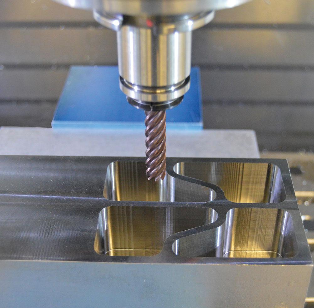
The Sandvik Coromant CoroMill Plura HFS end mills are developed for steels and stainless steel applications, but they can also enhance productivity in difficult-to-machine materials such as heat-resistant super alloys and titanium. Sandvik Coromant
Material removal rate (MRR) measures how much metal is removed from a component in a given period of time. In milling operations it can be calculated by multiplying the radial depth of cut (RDOC) by the axial depth of cut (ADOC) by the feed rate. An increased MRR—even just slightly—can have significant efficiency gains for any shop that is looking to produce more components in a short time. By increasing the MRR, shops are able to reduce cycle time and expand tool life, effectively driving down the cost per part and maximizing the profit margins.
High-efficiency milling (HEM) is a roughing strategy that can be used to help increase a machine’s MRR as it combines a lower RDOC and a higher ADOC, providing a consistent wear across the cutting edge, generating less heat, and allowing for increased speed.
HEM differs from traditional milling in two distinct ways. It allows for a controlled or consistent angle of engagement and radial chip thinning.
"Traditional or power milling works by using the entire diameter of the tool," said Brian MacNeil, milling products and application specialist, Sandvik Coromant, Mississauga, Ont. "This means there is significant tool engagement, often limiting the depth of cut. With a solid-carbide endmill or indexable mill, the entire length of the carbide, which is very expensive, is never used. On the other hand, HEM or high-feed side milling (HFSM) uses the entire length of the tool at a very low engagement. This allows for use of all of the carbide as well as radial chip thinning."
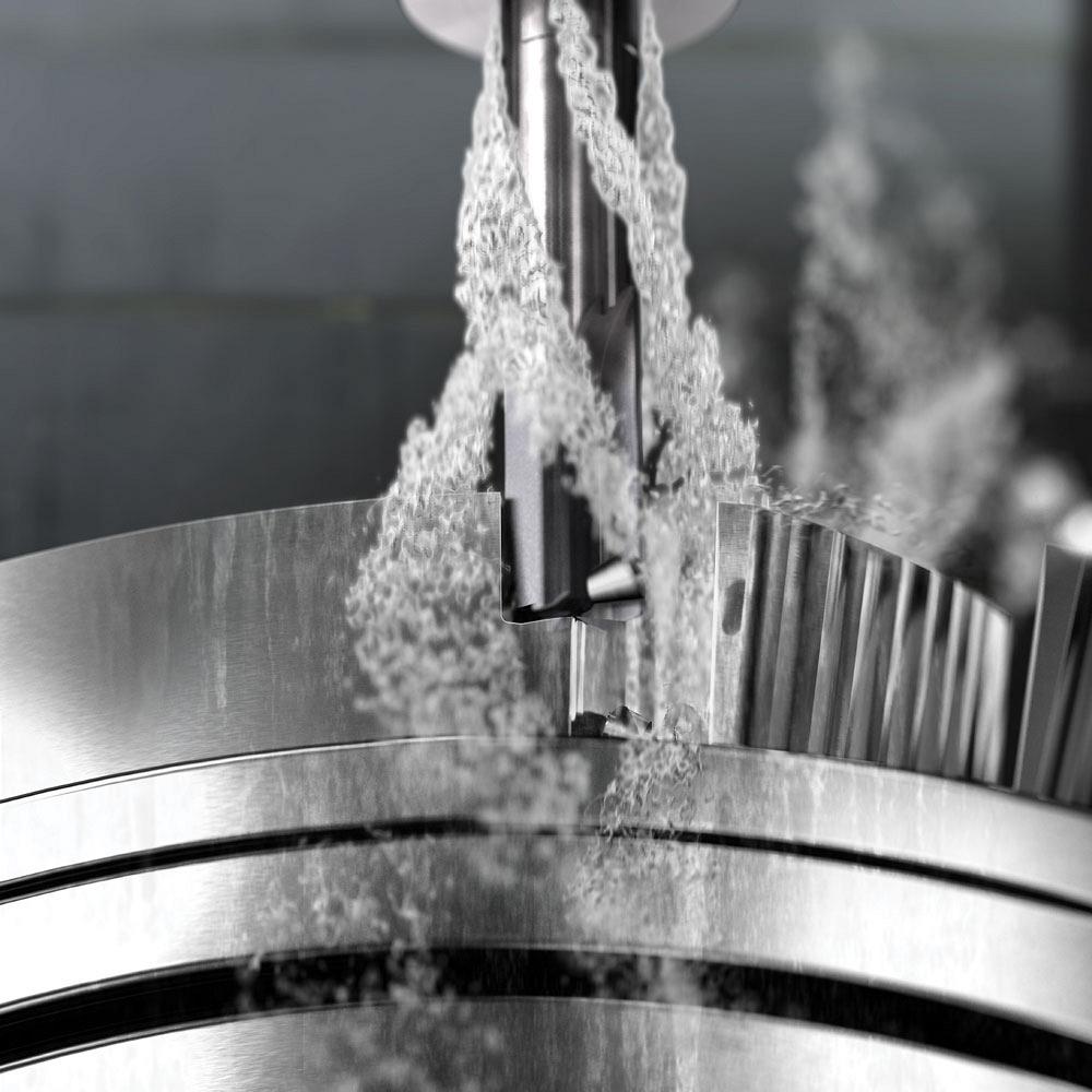
Reducing the engagement helps remove heat from the process, which allows for high-speed cutting. In heat-resistant materials, it helps extend tool life as there is less heat for the tool to deal with.
"HEM is typically more productive and requires less power than the old school types of toolpaths," said MacNeil.
Here are five ways to ensure that HEM is right for your shop.
"HEM definitely has its place, but it’s important to understand how it’s going to work," said Jake Rutherford, R&D engineer, Kyocera SGS Precision Tools, Cuyahoga Falls, Ohio. "It’s not a one-size-fits-all solution to every problem. You have to look at the application as a whole to make sure that it is the best and most efficient option."
One way to determine if HEM makes sense for the application is through testing. Many cutting tool manufacturers will perform testing in-house to help customers understand the process and see exactly how it would work on the shop floor.
"We can test several different types of toolpaths and strategies depending on the intended goal," said Jacob (Pete) Rak, applications engineer, Kyocera SGS Precision Tools. "The bottom line is what is your goal? If cycle time is a concern, which it often is, then HEM is a good strategy. If not, then maybe it’s not worth investing in all that is needed for it."
The Kyocera SGS H-Carb seven-flute High Efficiency end mill specializes in deep axial trochoidal and high-speed machining applications. The specialized core and flute design improves rigidity and chip flow while reducing deflection. Kyocera SGS Precision Tools
When shops first start employing HEM, a speed test can help give them a better sense of the process. Using a specific tool and program, the test can help determine the limits of the machine and the point where it might induce vibration.
"Knowing the limit of the machine and testing that before you start to employ these strategies is very important," said MacNeil. "Shops want to just jump in and not bother with it, but preplanning can be critical for success, especially for lights-out operations."
HEM is, for the most part, a particular type of toolpath and is based on a trochoidal milling style. It provides easy entry and exit of the cut. A traditional toolpath provides a more standard stepover into the material, which tends to be more abrupt and harder on the tool. An HEM toolpath is more gradual and can utilize more flutes in the tool because it eliminates overloading the flutes with material.
"The right CAM software is one of the first things required for HEM to be successful," said MacNeil. "Most systems now are capable of generating these constant engagement toolpaths. Some shops that don’t have that technology would have to purchase it. But you absolutely have to have CAM software that can apply constant engagement because if you start to overload it in certain sections, it tends to induce vibration, which can chip carbide and leave poor finishes on the workpiece."
For example, if the CAM software has been told to use 8 per cent of the tool diameter, it’s important that it always remains at 8 per cent. This will help prevent the tool from exiting and entering the cut all the time. Software that keeps the tool engaged is necessary.
"A lot of CAM software now has some sort of HEM toolpath built in," said Rutherford. "It’s just a matter of selecting it. When you choose that toolpath, it doesn’t necessarily have to be a higher flute-count tool, but to utilize the flute length and feed rates, a higher flute count tool is often the best option to reap the benefits."
One challenge with HEM is that some shops will try to perform high-feed side milling at extreme feeds on machines that are not capable of doing it.
"If the computer control can’t read all of the code, it’ll tend to bog itself down and start to pause," said MacNeil. "This process requires continuous cutting motions— once you start moving the tool, you don’t ever want it to stop, if possible. If the control can’t keep up, you’ll see problems in your workpiece, chipping of the tool, and defeat the whole point of the process."
The machine tool needs to have sufficient look-ahead capabilities; without this, it will be jolting around or jumping from one spot, reading a couple of lines of code, then jumping to the next.
"This will put a lot more load on the tool and destroy any cycle time gains," said Rutherford. "You can program 500 IPM, but if your machine can’t read that many lines of code or isn’t able to get up to that speed in that short amount of space between lines in the code, it won’t be able to achieve the full 500 IPM. Before jumping into HEM, make sure the machine has all the capabilities needed to get the job done."
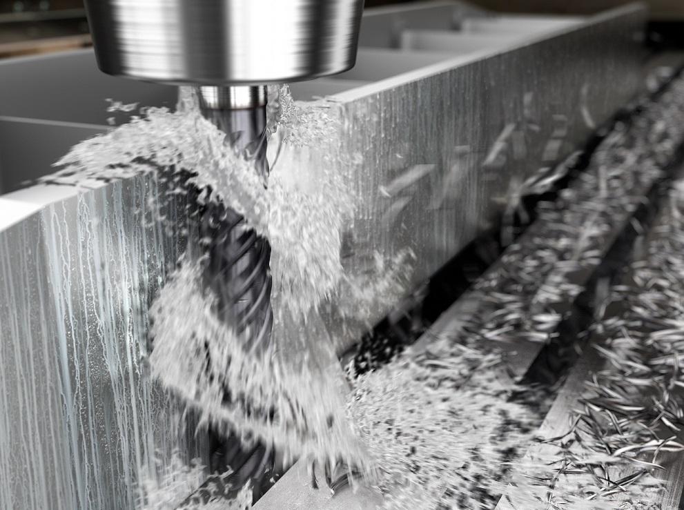
Some solid-carbide end mills, like Sandvik Coromant’s CoroMill Plura Gannet, have specifically designed geometries for plunging out material on deep, narrow slots. Sandvik Coromant
The higher the metal removal rates get the more important toolholding becomes.
"If you’re not holding onto the tool properly or using inexpensive toolholders, such as ER collets, the helical and axial cutting forces can actually suck the tools right out of the holder," said MacNeil. "Choose something like a hydraulic chuck or heat-shrink toolholder, but Weldon holders are still very effective. However, with hydraulic chucks and heat shrink, you get very low runout on the tool itself, but if you allow the tool to start to wander it will leave poor surface finishes. Essentially, this would cause only half of the flutes on the tool to be used when it’s running out and up. It will double the chip load."
Testing to make sure that the toolholder is providing an accurate and precise runout—one that is low—is important. HEM is particularly sensitive to high runout. Because of the combination of a higher flute count and a longer cut length, this process accentuates any runout at the end of the flute.
"Essentially, this would mean that one flute is doing a lot more work than another flute," said Rutherford. "There’s a lot less room for error than with a three- or four-flute endmill that takes a heavier chip load, and the reduced chip space cuts down on that margin of error even more."
The toolpaths created for HEM are effective only if the correct tool is used. Without a tool designed for HEM, the expected benefits may not be realized.
"To really optimize the process, take deep cuts with a long flute length," said Rak. "You generally will see a longer flute length than standard tools. A chipbreaker will also help break up long chips so they are evacuated easily out the cut zone. A high flute count tool will be more rigid, which is important for taking those deep cuts and utilizing the HEM toolpath for high removal rates."
Most tooling companies have cutting tools designed specifically for this application and are generally in the 4 to 5xD range, which tend to have conical cores. A single-diameter core all the way to the bottom tends to be weaker than a tapered core and doesn’t offer the same ability for chip evacuation.
"Tools designed with varied flute helixes is another way to ensure a smooth cut," said Mac-Neil. "On a four-flute tool, the first and third flutes would be 37 degrees whereas the second and fourth flutes would be at 40 degrees. Varied helixes create a slight pause from one flute to the next, and that gap will often prevent harmonics from developing. Tools with cylindrical lands and features behind the cutting edge help stabilize the cut at such high metal removal rates."
Michael Bitner, director, product and applications, milling, Dapra Milling Solutions, Bloomfield, Conn., discusses how high-feed ramping can help increase material removal rates.
CM: What is high-feed ramping and how does it work?
Michael Bitner of Dapra Milling Solutions discusses how high-feed ramping can help increase material removal rates. Dapra Milling Solutions
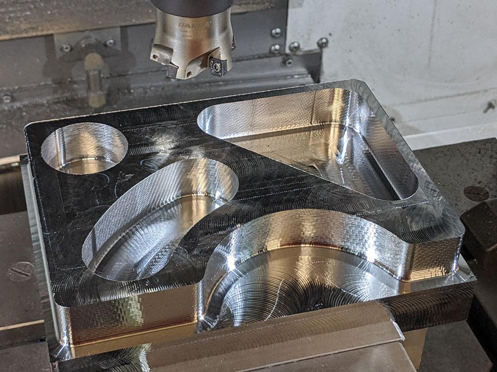
Bitner: High-feed ramping involves programming a high-feed cutter in a constant ramping motion while profile milling an internal or external shape. Generally, the cutter is just over half the smallest width of the internal opening being machined, or is bigger than the width of cut for an external shape being contour milled. By executing a constant ramp while profile milling a pocket or contour, the tool enters into the material from above and does not leave the cut until it reaches the final depth. This eliminates entry and exit moves, keeping the tool pressure constant.
CM: What requirements are needed for this to be effective?
Bitner: The CAM software must be able to generate a ramp profile routine versus a traditional 2D contour milling program. The ramp depth typically can be specified either with a depth per pass around the contour or through the specification of a ramp angle.
CM: What are the benefits and challenges of high-feed ramping?
Bitner: Benefits include the following:
Challenges include the following:
CM: What best practices should shops employ?
Bitner: For internal cavities, utilize a tool that is slightly over half the width of the narrowest dimension of the opening to be machined. For pockets that are too large to machine with one pass around, offset the profile to create a smaller internal pocket to machine and then move out to machine the outer pocket.
For external contour work, simply make sure that the cutter is larger than the widest width of cut (WOC) so that all material is removed with each pass.
In both cases, run the cutter at normal high-feed parameters, making certain to keep the depth of cut while ramping within the insert maximum. For this reason, it is generally advisable to specify a depth for ramping versus specifying a ramp angle.
CM: What misconceptions or mistakes surround this technology?
Bitner: If this type of programming hasn’t been used by the customer before, be careful not to confuse constant ramping with a ramp entry. A ramp entry simply ramps to the programmed depth of cut and completes the pass at that Z-level. A correctly programmed high-feed ramping routine will be constantly ramping from beginning to end, other than a flat pass once the final depth has been reached.
The other main mistake is underestimating the amount of air volume needed to evacuate chips adequately. Chips are being produced at an extreme rate, and failure to provide enough air pressure (and multiple air lines) can result in recutting of chips or chip packing, either of which can result in insert breakage or tool damage. With great productivity comes enhanced chip removal requirements.
Associate Editor Lindsay Luminoso can be reached at lluminoso@canadianmetalworking.com.
Dapra Milling Solutions, www.dapra.com
Kyocera SGS Precision Tools, www.kyocera-sgstool.com
Sandvik Coromant, www.sandvik.coromant.com


Keep up to date with the latest news, events, and technology for all things metal from our pair of monthly magazines written specifically for Canadian manufacturers!
Start Your Free Subscription
Easily access valuable industry resources now with full access to the digital edition of Canadian Metalworking.

Easily access valuable industry resources now with full access to the digital edition of Canadian Fabricating & Welding.