


product marketing manager
With so many variables in the cut quality equation, there are many things that fabricators need to know before starting. The first step is to ensure you are using the correct set of consumables. Remove your consumables from the torch and open your owner’s manual to the cut chart for the process you are using.
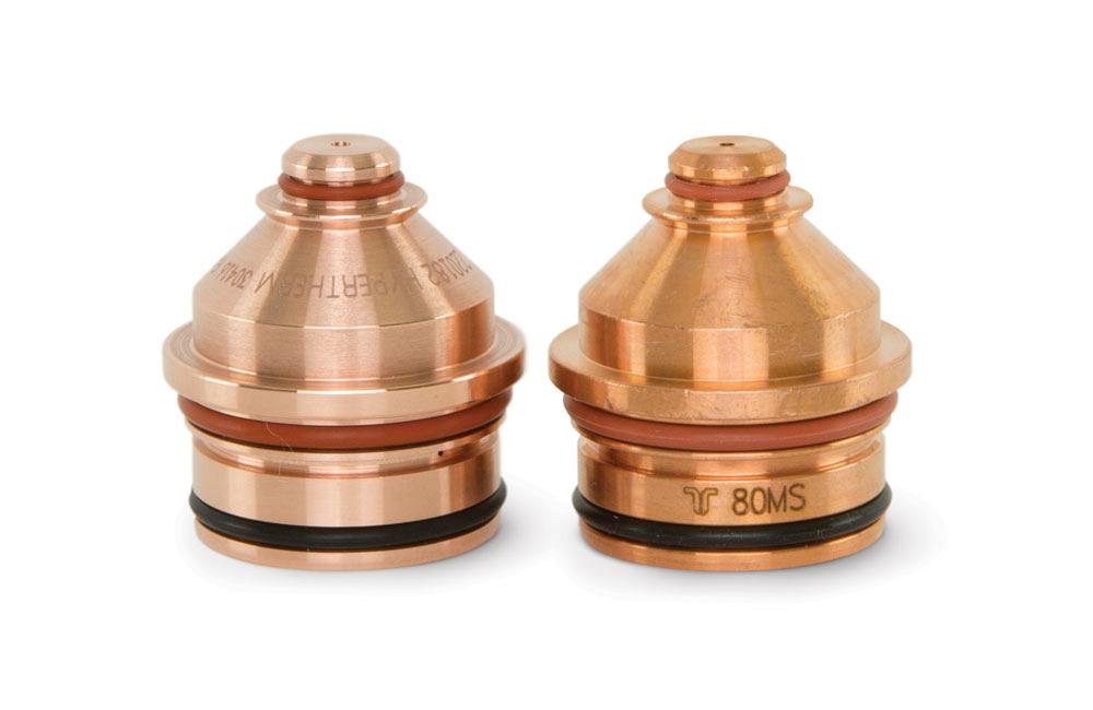
If you want to cut mild steel at 80 amps using an O2 plasma/air shield process, turn to that chart in your manual and verify that the part numbers marked on the side of each consumable match.
This is also a good time to check the condition of your consumables, including the swirl ring, shield, nozzle, and retaining cap, to ensure they are still usable. If any of the parts look questionable, install a fresh set, taking care to assemble everything in the correct order using clean, dry hands. Eight or nine of every 10 cut quality problems are fixed by replacing the consumable parts.
If you are still not satisfied with the cut quality, it will be important to identify what specific attribute you are not happy with—bottom dross, top dross, top edge rounding, surface finish, or angularity. Once you’ve identified the specific attribute you are unhappy with, you can call your cutting table manufacturer and start to troubleshoot the problem.
The most common causes of cut quality problems are:
Bottom dross, when globs of metal form along the bottom of the cut edge, can be caused by a number of things, but the most common cause is cutting at the incorrect speed. When the cut speed is too slow, the plasma arc starts to look for more material to cut. The arc column grows in diameter, widening the kerf to a point where the high-velocity portion of the plasma jet no longer blows the molten metal away from the cut and instead causes it to accumulate along the bottom of the plate. You need to be careful, though, because if you cut too fast, you can wind up with high-speed bottom dross. This type of dross is much harder to remove than its lowspeed counterpart.
To find the dross-free window, often called the dross-free zone, you will need to make speed adjustments from the set point in your cut chart. For example, if your cut chart calls for a speed of 130 inches per minute when cutting ½-in. mild steel with O2 and air, that’s where you should start, slowly increasing and decreasing the speed until the dross disappears. It’s recommended that you increase the speed in 10 per cent increments from the set point, and then decrease in 10 per cent increments, again from the set point. This should provide you with a fairly accurate dross-free window.
If you get to a point where you start to see dross along the top edge of the cut, you’ve passed through the dross-free zone and are seeing dross because you are going too fast. In this case, you’ll want to back off on the speed and instead adjust your amperage and standoff from the plate, as cutting at an amperage that is too high or a standoff that is too low can also cause low-speed dross. This is because both situations cause more energy from the plasma arc to contact a given area of the metal.
If you are having an issue with dimensional accuracy, start by looking at your torch to be sure it is aligned at a perfect 90-degree angle to the plate. If it is, look at the slats on your cutting table. If the slats have too much slag, the plate won’t sit level and cuts with angularity will be produced. The third thing to look at, once you’ve ruled out items 1 and 2, is your cut height. Energy density, gas velocity, and other factors influence the plasma arc geometry, but for illustration purposes, think of the plasma arc as a candle flame. It is tapered at the top and bottom and widest in the middle.
If your cut height isn’t right, because the torch is too close or too far from the plate, the arc won’t hit the plate at this widest point, creating a cut with more angularity. The solution then is to use the cut height found in the cut charts and make small incremental changes from there.
If you are not satisfied with the cut quality, it is important to identify what specific attribute you are not happy with—bottom dross, top dross, top edge rounding, surface finish, or angularity.
Before cutting begins, verify the consumables are in good condition. Using worn parts on the torch is the main cause of interrupted cuts in the middle of a nesting program. Also, verify that your part or nesting program matches the size of your plate. This will prevent a scenario in which the torch runs off the plate while cutting.
Most CNCs will allow you to resume the cut when the cycle is interrupted.
True Hole technology takes the guesswork out of cutting holes with a 1-to-1 all the way up to a 2-to-1 ratio by automatically applying the best process parameters for a given amperage, material type, thickness, and hole type. This makes it easy to dial in great holes because you aren’t having to play around with a lot of settings, like gas type and flow, speed, the timing of your arc-on and arc-off, and lead-in length.
If you don’t have access to this technology and are cutting holes outside the 1-to-1 and 2-to-1 range, you can still improve the holes you are producing, but it will require a little more work and experimentation. Here are some general rules to follow.
Slow down. When you slow down the torch speed for holes to at least half the speed of perimeter cuts, the bottom half of the plasma arc can catch up with the top half of the arc, thus minimizing lag and the taper of the hole.
Lock the torch in place. As the cut speed is reduced, torch height control systems become less stable. A way of compensating for this is to "freeze" the height control axis at the recommended height for all holes under 1 in. This ensures greater uniformity in the cylindricity of your holes and minimizes the chance of collisions between the torch and the material.
Play with the lead-in and leadout. If you do not have nesting software to do the design work for you, you’ll need to draw the lead-in and lead-out into the DXF post. When cutting holes, try to get the pierce as close as possible to the centre or middle of the hole, and then create a circular path or curve from the centre out into the radius of the hole. Lead-out is also known as an overburn, which is when the torch travels past the starting point in the radius of the hole. The overburn will clean up the hole a little.
Jorge Santana is the product marketing manager for Hypertherm HPR and XPR Plasma, 21 Great Hollow Road, Hanover, N.H. 03755, 603-643-3441, www.hypertherm.com.
Photos courtesy of Hypertherm.


Keep up to date with the latest news, events, and technology for all things metal from our pair of monthly magazines written specifically for Canadian manufacturers!
Start Your Free Subscription
Easily access valuable industry resources now with full access to the digital edition of Canadian Metalworking.

Easily access valuable industry resources now with full access to the digital edition of Canadian Fabricating & Welding.