Editor
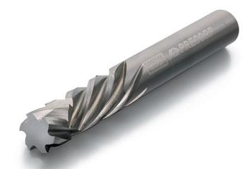
Tool selection for high-speed machining is similar in nature to any other milling operation: It begins and ends with the workpiece. The material, size, and features of the part will determine what tool is best.
High-speed machining, specifically milling, has the same variables as traditional milling. There are speeds and feeds to set and a depth of cut to be determined. However, in a high-speed machining operation, slow, heavy cuts are replaced by fast, lighter cuts.
While it may seem counterproductive to take lighter cuts when heavy cuts are possible, shops that can make this switch in thinking will produce accurate parts faster.
Defining high-speed machining is difficult because it can be one of many operations, or a combination of them. It can be defined as:
High-speed machining is not defined, however, as machining with a high material removal rate using a large axial depth of cut (Ap) or large radial depth of cut (Ae).
“High-speed machining typically is a combination of fast movements,” explained Kevin Burton, product specialist for Sandvik Coromant Canada. “To achieve the best results possible, these applications need to be well planned out. If you are using a high-speed process, but tool life and part quality are not within acceptable levels,you have implemented it improperly.”
Five areas require consideration before the tool ever meets the workpiece. They are:
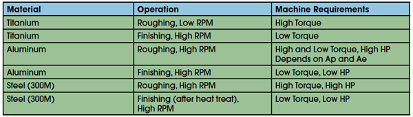
High-speed machining is popular in both the aerospace and die/mold sectors. Because of this, the metals seen most commonly in these applications are titanium, steels (including stainless steels), and aluminum.
Each of these metals has its own characteristics, so high-speed machining is defined differently for each.
For example, the high-speed machining of titanium takes place during the finishing stage. While the feed remains the same, the surface feet per minute (SFM) can triple. Also, during the roughing stage, RPMs are kept low, but during finishing, RPMs are high.
Titanium (roughing stage)
SFM: 80 to 180
Feed: 0.002 to 0.005 in.
RPM: low
HP: low
S torque: high
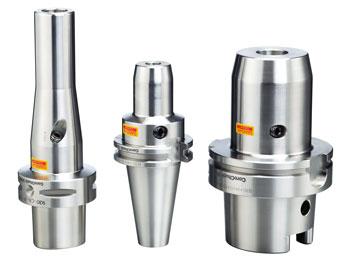
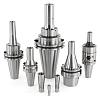
What is most important in high-speed machining is that the tool be properly held and balanced.
Titanium (finishing stage)
SFM: 200 to 600
Feed: 0.002 to 0.005 in.
RPM: high
HP: low
S torque: low
“There is a conundrum when selecting a machine tool for high-speed machining because as the material changes, the torque and HP requirements of the machine also change,” said Burton.
This means that a machine that is suitable for the high-speed machining of titanium may not be suitable for another material, such as 300M.
“Before starting any high-speed operation you need to examine the machine tool’s power/torque graph to make sure that the machine will be able to handle the requirements that are needed,” said Burton.
“Quite often during these operations the machine will operate at the two extremes of its capabilities,” said Brian MacNeil, product specialist for Sandvik Coromant Canada. “Therefore, it’s extremely important to apply the correct machining strategy.”
Proper cornering and chip-thinning techniques need to be applied. These typically include rolling in on entry and out on exit, corner radius feed compensation, and the trochoidal milling technique.
Conventional milling runs the cutter in a straight line and typically has a heavy chip load. With trochoidal milling, the cutter moves in a circular motion and has a low but constant chip load.
Constant stock removal and chip load will enable the high-speed machining process to be productive and secure, while producing the surface quality that is desired. This is accomplished by minimizing changes to work load and direction.
“Using proper techniques also will keep you from overloading the machine,” said MacNeil.
Tool selection for high-speed machining is similar in nature to any other milling operation: It begins and ends with the workpiece. The material, size, and features of the part will determine what tool is best.
What is most important in high-speed machining is that the tool be properly held and balanced.
“Lack of stability in the tool generates vibration, which shortens tool life,” said MacNeil.
In fact, for every 0.01 mm of runout, tool life can be reduced by as much as 50 percent. Runout also lowers the quality of the surface finish.
Fancy mathematical equations involving Newton’s second law are used to calculate tool imbalance and eccentricity, but what’s important for machine shops to know is that even the smallest amount of imbalance at high speeds can cause major problems in eccentricity.
Sandvik Coromant calculated the consequences of imbalanced forces by adding a sticker to one side of its toolholder, a practice common in many shops used to differentiate tools quickly.
The company added a 0.25-gram sticker to a 1.25-kg, 40-taper, perfectly balanced tool and found that this tiny addition caused 12 N of imbalance force at 15,000 RPM.
Balancing a tool rotates it to produce centrifugal forces and then measures the forces at the spindle bearings. This will determine the size and direction of the imbalance at a given height.
“Balance is important,” said Burton. “When a tool is out of balance, it is detrimental to the machine’s spindle, and tool life will go down dramatically.”
7 Steps to Balancing a Tool
“Shops that are looking to add high-speed machining capability need to have a machine tool that can provide the necessary motion, the necessary CAM capability, and a control with a good look-ahead function,” said MacNeil.
The correct CAM software enables complex, 3-D, contoured surfaces to be created and helps keep the chip load and travel speed consistent.
“There really are a number of factors that determine if a high-speed application will be successful,” said Burton. “The cutter, machine tool, control, and software are all part of it.”
“If all you are doing is running at a really fast spindle speed, you are not getting the most out of the process,” added MacNeil.


Keep up to date with the latest news, events, and technology for all things metal from our pair of monthly magazines written specifically for Canadian manufacturers!
Start Your Free Subscription
Easily access valuable industry resources now with full access to the digital edition of Canadian Metalworking.

Easily access valuable industry resources now with full access to the digital edition of Canadian Fabricating & Welding.