


What Type of Automation Is Right For You?
Consider part size, weight, complexity, other factors when automating a process
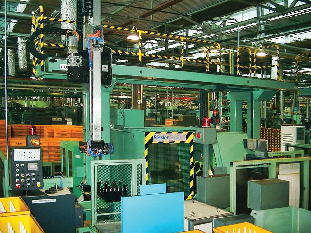
This single-arm gantry is used for a cutting machine load/unload cycle.
With all the choices available for automated machine tending, a best first step is to involve an engineer familiar with the characteristics of hard automation, linear motion, and robotics.
Companies that specialize in linear motion for robots offer engineering studies and assistance to ensure proper application of everything from fixed-location robots to floor-mounted and overhead robots to full area gantries. Involving them early in the design stages of a load/unload system saves time and money now while avoiding costly re-engineering later.
Many factors should be considered when selecting an automated machine tending system.
Primarily, the number of machines and actual physical space needed, including factors such as floor space and ceiling heights, should be addressed. The cycle time for each machining process—the time that the machine needs to process the part; load/unload time; and critical issues unique to a certain process, like minimizing mold open time in an injection molding machine to minimize heat loss--all must be decided next.
The right combination of machines must be selected with the goal of meeting throughput requirements, using each machine efficiently, but also with a correct balance among the cycle times of each machine. More machines means more part transfers, which means more chance for part damage. However, fewer machines may not meet the throughput requirements.
To limit machine changeovers, you can do some work in a single, complex machine.
After the machines and layout are chosen, ask these 10 main questions:
1. Is the sequence of operations consistent for all the parts to be run through the line?2. Where can the machine tending device access the parts?
3. What motion is required to load/unload parts?
4. How will large parts be handled?
5. What type of clearance is needed to get the parts in and out of the machine?
6. Do building features, such as columns and low ceilings, get in the way?
7. How will machining fluids and air get routed to the entire system?
8. Can vision systems or other sensing technologies reduce the need for part handling and positioning?
9. Should custom end-of-arm tools (EOAT) be ordered to handle multiple parts?
10. Can the automation be bypassed and the machine loaded manually in the event of a malfunction in the automation?
Reasons for Automation
Manual machine loading and unloading can be tedious, inefficient, and in some cases dangerous.
This means that load/unload operations can have significant impact on the cost and quality of the product and on the safety of the personnel.
It is important to identify the key reasons to automate. These reasons will guide your selection of appropriate methods and support the level of expenditure required.
The need for automation, and the type of automation, depends upon two factors. First is the quantity of parts to be run per hour and second is the total number of parts being produced. These two factors will then influence the required speed of the part handling system and needed machine uptime and efficiency.
The size and weight of the parts to be handled, size of the machines being tended, and the machining environment (hot, wet, cold), also need to be taken into account. Also important to note are the quality requirements for the parts, part tracking, and cost and availability of labor.
What You Can Expect From Automation
- Maximized throughput due to high reliability and consistent cycle time performance.
- Increased system uptime.
- Improved process flow and use of floor space.
- Improved just-in-time (JIT) manufacturing with reduced work-in-process (WIP).
- Improved worker safety and ergonomics.
- Minimized errors through the use of sensing and errorproofing technologies.
- Improved data collection and part tracking.
- Reduced cost per part.
The Choice for Automatic Load/Unload
The choices for automating load and unload of machines range from hard automation to very flexible, reconfigurable automation systems for both single machines and multiple machines.
The Choices:
1. Hard automation. Hard automation typically refers to simple pick-and-place devices that have a fixed motion stroke, albeit often in more than one axis. For this, linear-motion devices actuated by pneumatic cylinders or motors with drive belts utilizing limit switches to define their intended positions for pickup and dropoff are used. These are configured for a particular application and typically will need to be reconfigured physically, rather than reprogrammed, to accommodate other part designs or process changes.
What you need to know:
- Lower cost to implement (but often more total cost of ownership over time)
- Best for a part that does not change in size or design
- Simple process, no complexity of motion
- Typically most suitable for small work envelope
- Limited redeployment to another application
- High performance, repeatability, and speed
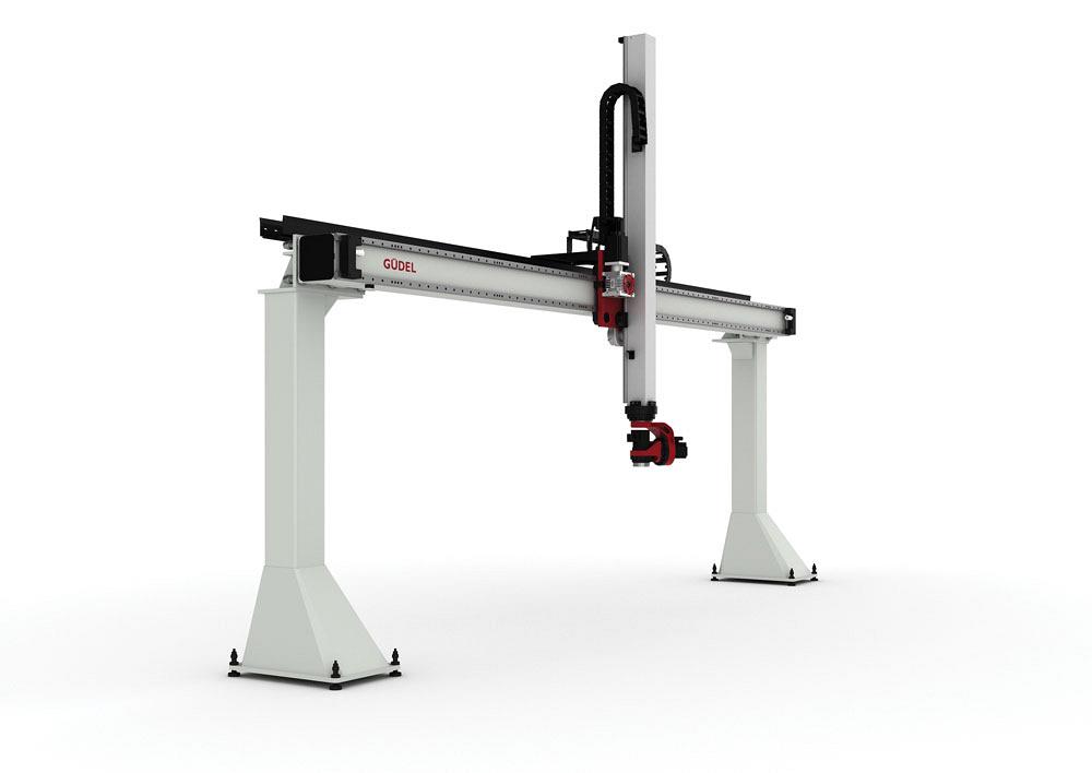
2. Fixed-position robot. This single, multiaxis (typically a 4- or 6-axis) robot is mounted in a fixed position near or even inside a single machine tool. For a robot in the machine tool to exist, it must be able to withstand the environment in the machine (often cutting fluids or heat) and is typically dedicated to machine load/unload.
An externally mounted robot often can move the part to secondary operations, such as gauging or trimming processes.
What you need to know:
- Can access the machine load/unload positions from the front
- Complexity of motion requires 6-axis device
- Reprogrammable and flexible for part changes, repurposing, part changeovers, tooling changes
- Ability to reach everything required to load and unload and any peripheral equipment
- Ability to do the operations required in the cycle time available and no additional time available to do other work with this robot
- Repeatability varies from +/-0.01 mm to >+/-0.20 mm depending on the robot model
- More intensive programming capabilities required
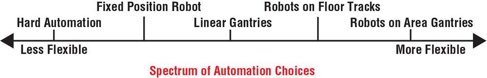
3. Overhead gantry. These devices can be mounted over a line of machine tools and move parts between those machine tools or to secondary or staging operations. Multiple Z-axis gantry arms can be used on a single beam, providing increased throughput capabilities for the system. Overhead load/unload configurations provide easier maintenance access to the machine tools.
What you need to know:
Linear gantry robots can be integrated with other automatic machining, welding, and robot assembly equipment.
- Can access the machine load/unload positions from the top or with a small movement into the machine from the front
- Need relatively simple X-Y-Z-R movements with the parts being transferred
- Multiple machines on the same part placement centerline can be serviced by a single device
- Need to minimize use of floor space for parts transfer between operations
- Repeatability of +/-0.05 mm
- Cycle times can be reduced with one, two, or more gantry arms
- Flexible for part changes, repurposing, part changeovers, tooling changes
- Choice of CNC or PLC programming
- Linear gantries can do secondary operations while moving parts from machine to machine
4. Multiaxis robot on a floor track. This type of system allows the robot to move between multiple machines and secondary processes. Now the work envelope of the robot is increased, allowing a single robot to service multiple machines.
In fact, more than one robot can be mounted to a single track to foster higher system throughput. With this track configuration, the robots can be moved aside to facilitate machine tool maintenance.
What you need to know:
- Can access the machine load/unload positions from the side or top
- Option to make more complex 5-to-7-axis motions with the part
- Multiple machines that can be arranged in a line if cycle time is long enough for one automation device to tend multiple operations
- If cycle time is tight, sometimes it is possible to split the work between two or more robots on the same track
- Have the floor space and would like to keep all equipment on the floor
- Repeatability for track is +/-0.05 mm
- Robots can do concurrent operations while moving parts from machine to machine with more complexity—part reorientations, part cleaning operations, inspections, etc.
- Vision guidance can be used for picking or tracking parts in 2-D or 3-D
5. Overhead track. For increased capabilities, especially if part articulation requires a 6-axis robot, it is also possible to mount a 5- or 6-axis robot on an overhead track. This configuration provides the ability to reach an area under the gantry with the use of a single overhead rail, and it adds the ability to rotate parts with the servo control of a robot wrist. Multiple robots are easily mounted to a single overhead track to increase throughput.
What you need to know:
- Can access the machine load/unload positions from the side or top
- Need option to make more complex 5- to 7-axis motions (or more) with the part
- Need significant Z-axis stroke, but don’t have the ceiling height for a vertical Z-axis gantry arm
- Have multiple machines and suitable cycle time for one or more automation devices in a line to tend multiple operations
- Wider work envelope needed than what can be achieved with a linear gantry
- Narrower work envelope needed than what is achievable with an area gantry
- Need to minimize use of floor space for parts transfer between operations
- Repeatability required is +/-0.05 mm
- Robots can do concurrent operations while moving parts from machine to machine with more complexity
- Vision guidance can be used for picking or tracking parts in 2-D and 3-D
6. Area gantries. For a large work area, a 5- or 6-axis robot on an overhead area gantry provides extended coverage for machines along with the ability to manipulate parts with a servo-driven 3-axis robot wrist. And, of course, multiple robots can be mounted to a single overhead track to increase throughput.
What you need to know:
- Can access the machine load/unload positions from the top or side
- Need relatively simple X-Y-Z-R movements with the parts being transferred
- Need to access a wide area with multiple machines or part pickup and dropoff points
- Minimize use of floor space for parts transfer between operations
- CNC or PLC programming
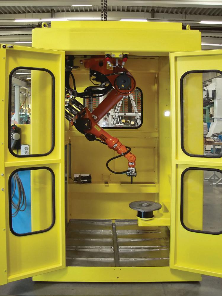
This internally mounted 6-axis robot is used for tending a grinding machine.
subscribe now


Keep up to date with the latest news, events, and technology for all things metal from our pair of monthly magazines written specifically for Canadian manufacturers!
Start Your Free Subscription- Stay connected from anywhere

Easily access valuable industry resources now with full access to the digital edition of Canadian Metalworking.

Easily access valuable industry resources now with full access to the digital edition of Canadian Fabricating & Welding.
- Trending Articles