


Finish Turning
Optimizing the finish pass for desired surface finish requirements means examining more than just the tool
When turning the finishing pass of a part, the tool produces tiny, threadlike grooves. Surface finish is measured as the depth of the small, threadlike grooves. The shallower the grooves, the better the surface finish.
The formula Ra = (IPR²/(8 x radius)) x 333.333 is a rather simple formula that takes into consideration only two factors: feed rate in inches per revolution (IPR) and the nose radius of the insert.
Of course, in the real world numerous other factors must be considered when finish turning. These include the machine’s spindle bearings, the condition of the ball screw, the part’s configuration, coolant flow, cutting tool material, and cutting tool shape.
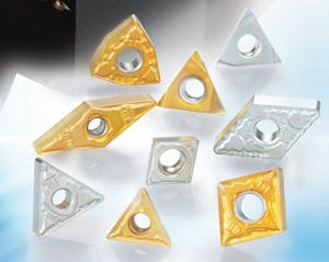
Cutting Tool Material
Inserts have a major effect on the surface finish. Common problems with surface finish caused by the insert are built-up edges (BUE) and flank wear. BUE occurs when the material being cut adheres to the insert. It can be prevented by running higher at RPM and using an insert with a slippery surface so the chip flows over the insert without sticking. A heavier flow of coolant also may help prevent BUE.
When the insert wears on the flank of the insert and creates an irregular surface at the cutting edge, a poor surface finish is created. Flank wear is inevitable as this is normal insert wear. Paradoxically, to prevent premature flank wear it is generally advisable to slow the speed, which may contribute to BUE. A solution to this problem is to finish turn using cermet inserts (see Cermet Tooling Explained).
Today’s cermets are much tougher than earlier versions. For example, Tungaloy offers a reinforced cermet that has the same transverse rupture strength as some carbide grades. North America has been slow to embrace cermets, with this type of tool representing less than five per cent of all cutting tool inserts sold. In the Japanese cutting tool market, 20 per cent of all cutting tool inserts are cermet.
Cutting Tool Shape
The geometry of the insert plays a defining role in surface finish.
Small parts or thin-walled parts may not be able to run negative inserts because the pressure created from these tools may cause chatter or even deform the part. In these cases it is recommended the machinist use a positive geometry insert. Poor spindle bearings or bad ball screws may also require the use of positive geometry inserts.
Another factor of cutting tool shape is whether or not to use wiper inserts. Wiper inserts have a small trailing edge just behind the nose radius that “wipes” or pushes down the peaks of the tiny thread like grooves creating a better surface finish. The use of a wiper insert may increase pressure and is not advisable in all applications. Wiper inserts only typically work on straight surfaces and will not work on tapered part configurations.
Controlling Finish
Insert nose radius and feed per revolution are the easiest factors to control when finish turning.
Surface finish is measured as the depth of the small, threadlike grooves produced by the finishing pass.
Obviously the larger the nose radius, the better the surface finish, and a slower the feed rate will also create a better surface finish.
One factor that is often overlooked when trying to improve a finish turning application is the toolholder. If the toolholder is old, and the pocket that holds the insert is worn, the insert may move. Any movement of the insert will create chatter and result in poor surface finish.
The application of coolant will help cool the insert and create a slippery surface for the chip to flow over the insert without creating BUE and care should be taken in directing the coolant flow.
As the part is being machined, the chip comes off the part and creates an umbrella, blocking the coolant from reaching the cutting area. The coolant should be directed in such a manner as to get under the chip. Often, having the coolant approach the part from the side, or slightly under the holder, can prevent the umbrella effect caused by the chip formation.
For more information, visit www.tungaloyamerica.com.
subscribe now


Keep up to date with the latest news, events, and technology for all things metal from our pair of monthly magazines written specifically for Canadian manufacturers!
Start Your Free Subscription- Stay connected from anywhere

Easily access valuable industry resources now with full access to the digital edition of Canadian Metalworking.

Easily access valuable industry resources now with full access to the digital edition of Canadian Fabricating & Welding.
- Trending Articles