


Machining in 3-D
High-feed milling should be considered to improve Q rate, reduce cycle time
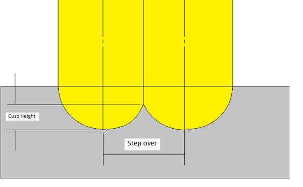
Figure 1
As the tool cuts, cusps are created, forming a wave pattern in the material. This can increase the amount of hand polishing necessary for a mold.
As its name implies, 3-D machining is the removal of material in all three dimensions, whereas face milling, for example, primarily is the removal of metal in two dimensions.
Three-dimensional machining, most often used in die- and moldmaking applications, usually begins with a block of material that is removed until the desired part configuration remains. This process is sometimes referred to as subtractive manufacturing.
However, an emerging technology is additive machining. It begins with a CAD program created using a 3-D modeling program. The software slices the model into thousands of tiny horizontal layers, and once prepared, the information is sent to a 3-D printer.
The printer then lays tiny layer upon tiny layer until the desired configuration is completed. In this case, the term “3-D printer” may be a little misleading because the part actually is produced by layering a series of thousands of thin 2-D layers.
Machining in 3-D
For machining a 3-D part, high-feed milling is recommended to rough the part. High-feed milling uses a light depth of cut (DOC) and an extremely fast feed rate.
Just as 3-D printing is thousands of 2-D layers, high-feed milling movements also are a series of small 2-D layers. While the 3-D printing process adds material, high-feed milling removes the material, leaving only the material that makes the desired part configuration. Just as with 3-D printing, the smaller the layer, the closer the finished part is to the desired form.
Conventional wisdom for roughing a 3-D part has always been to use a large DOC. A recent trend though is to perform roughing with high-feed milling, which typically uses a DOC between 0.020 and 0.120 in., but at extremely high feed rates. The metal removal rate (Q), as measured in cubic inches of material removed per minute, often is better than the conventional large DOC method. This means that even though the DOC with high-feed milling is much less, the cycle time is dramatically reduced.
Because the thin layers removed with high-feed milling bring the part closer to its finished form, semi-finishing and finishing operation times are reduced, further reducing cycle time.
Switching to High-feed Milling
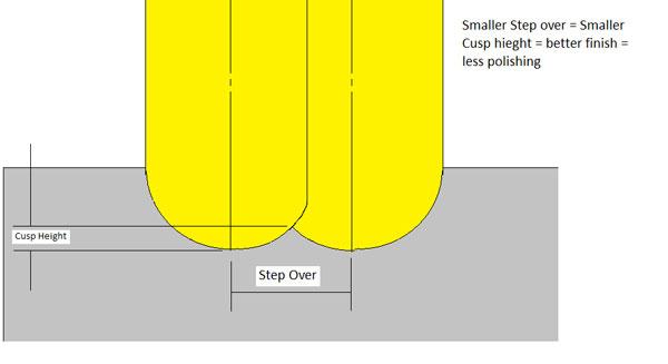
Figure 2
Reducing the stepover reduces cusp height, thereby improving surface quality.
Some machinists are reluctant to use high-feed milling because they believe running their machine at 200, 300, or even 500 IPM will be too hard on the equipment. However, during machining with a large DOC, the cutting forces act perpendicular to the spindle, putting incredible stress on the machine. Conversely, because high-feed milling cuts “under” the tool, the cutting forces act almost parallel to the spindle, putting much less load on the machine tool.
Even with the smaller DOC used during high-feed machining, the part still needs to be finished. A common tool used to finish 3-D parts is the ball nose end mill. This milling tool has the ability to profile complex contours by moving up and down the part’s shape. However, the ball nose end mill is not capable of producing a flat surface. As it cuts, the tool leaves a series of waves, also known as scallops or cusps (see Figure 1). And the higher the cusp height is, the worse the surface finish (Ra) will be.
Obviously, a smaller stepover creates a shorter cusp, and therefore better surface finish (see Figure 2).
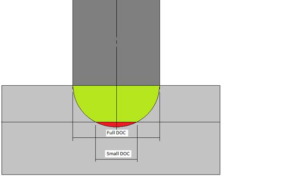
Revolutions per minute (RPM) is a key factor when programming a job to be finished with a ball nose end mill. An RPM that is too fast or too slow can reduce tool life and create a poor surface finish. When taking a light axial DOC, the diameter will be much smaller than when programming for a full DOC. Many programmers and machinists simply use the full diameter to calculate the RPM. Since RPM = (Recommended surface feet x 12) / (3.14 x Diameter), it is critical to program for the correct diameter. Generally, the smaller the axial DOC, the smaller the diameter (see Figure 3).
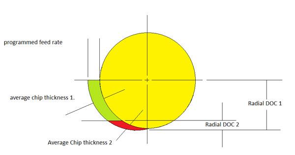
Another factor to consider is the radial DOC. In Figure 4 the radial DOC (cut 1) is equal to half the diameter of the cutter. The programmed feed rate will produce the desired average chip thickness.
However, with a light radial DOC as shown as radial DOC 2 in Figure 4, the average chip thickness is much less than the programmed feed rate. Therefore, to get the desired chip thickness, the machinist must increase the feed rate, often significantly. Machinists frequently slow down the feed when the desired surface finish is not produced. This is the wrong way to go. Slowing the feed rate creates a rubbing action, reducing tool life, producing a poor surface finish, and lengthening cycle time.
subscribe now


Keep up to date with the latest news, events, and technology for all things metal from our pair of monthly magazines written specifically for Canadian manufacturers!
Start Your Free Subscription- Stay connected from anywhere

Easily access valuable industry resources now with full access to the digital edition of Canadian Metalworking.

Easily access valuable industry resources now with full access to the digital edition of Canadian Fabricating & Welding.
- Trending Articles