


Business Development Manager, Threading
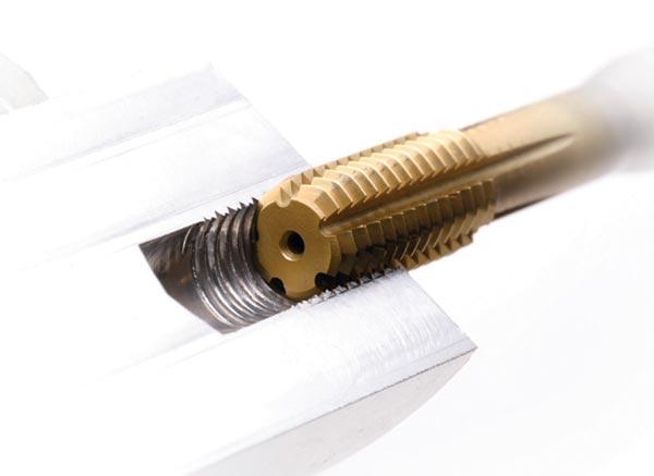
Roll form tapping as a chipless threading process requires excellent hole size and quality.
When diagnosing problems with internal threading, a machinist often overlooks the size and condition of the hole before threading. Of all the threadmaking processes, tapping seems to suffer the most from this oversight.
Thread mills will usually overcome the issues that can cause taps to fail, making them an attractive option for most applications. Other factors such as toolholding, workholding, machine condition, and lubrication also can have a significant effect on the tapping operation. A tap failure is usually blamed on a “bad” tool when, most likely, there is nothing wrong with the tap itself; it just might not be ideal for the machining conditions. It is crucial to look at the tapping process, not just the tool, to achieve a good finished product.
The first part of the threading process is always creating the hole. Stamping, flame or laser cutting, casting, milling, and drilling are common holemaking methods that yield completely different bore conditions.
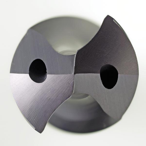
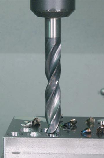
Solid-carbide drills tend to leave a more cylindrical hole with a better surface finish than HSS or HSS-E tools because of the higher stiffness of the tool material. The tool design also has a great impact on hole quality. A double-margin tool usually produces a better hole and more stable drilling conditions. However, the surface area of the tool rubbing against the part during drilling is essentially doubled, creating more heat that can cause other issues if not mitigated with coolant. Straight-fluted drills have a high core strength to resist flexing, yielding a very straight hole, but can cause issues with chip evacuation in long-chipping materials, which negatively affect the hole finish and size.
Point geometry can also affect bore dimensions. Many different point geometries are created for various reasons, from conventional nonsplit to Racon®, and everything in between. Full-split points tend to be the most successful for good hole dimension, as nonsplit pointed drills do not center very well and increase thrust load when drilling. Helical-point tools tend to work well by reinforcing the chisel edge to resist fracture, and they also center well. The center of the drill mainly extrudes material at low surface speeds until it is pushed into the flute area where it deforms and hardens to the point of fracture at high surface speeds.
Last, the flute and cutting lip geometry also influence the quality of the hole. Parabolic-fluted tools have a lot of space for chip evacuation and good strength properties, but tend to flex more than standard tapered-web or parallel-web drills. The flute shape and angle of the point create the cutting lip shape. Straight-lip drills tend to take the extrusion from the point that is being pushed into the flute area and cause it to curl and eventually break against the side wall of the bore. This can cause finish and work-hardening problems, but is a good design for use with multiple materials.
A lot of long-chipping materials benefit from drills with a concave lip, which causes the extrusion to curl tighter and break against itself. This reduces heat and wear on the side bore wall. However, it leaves a sharp point on the drill corner that is weaker than a straight lip. Convex-lip drills have also been made that greatly reinforce the point and cutting edge, but force the chip against the side wall. They work at much higher feed rates, but hole quality can suffer.
Indexable drills can have complex chip breaking geometries on the inserts that mitigate most of the problems faced by solid tools and are often a better choice for hole quality.
A bore that is not round can put more radial load on one side of the tap than on the other. That creates very high dynamic stress on the tool core, which ultimately leads to breakage. Similar conditions occur with a bore that is not straight; the farther the tap gets engaged in the bore, the more out of position it becomes, increasing the load on the core. A HSS tap may be able to handle the flex that is imposed by a hole that is not straight or out of position, but the problem gets compounded with stiffer tool substrates like HSS-PM or even solid-carbide taps that will shear very quickly.
A rough surface finish with a wavy texture leaves an uneven amount of material to be removed, stressing the core and teeth of the tap unevenly. The surface can also be affected greatly in materials that work-harden, such as stainless steel, titanium, and INCONEL® alloys, leaving a very hard skin above a softer base material and creating a challenge for the small rake face of the tap.

An even tool load is key to maintaining good chip control when tapping, particularly when creating blind holes.
Methods such as laser or flame cutting, stamping, and casting often leave a tapered hole that affects the tool by changing the amount of material to be removed during the following tapping process. This also leads to tool failure by creating too much torque on the tap. The same problem occurs with straight bores with a diameter that is too small for the corresponding thread. This problem frequently goes unnoticed, and most shops are not getting the full tool life out of their taps due to an inappropriate hole size.
The hole size before tapping is critical to keep enough material for adequate thread strength and to keep the torque low for long and consistent tool life. Notice that the emphasis should be on hole size, not on drill size. There is much more to the hole size than just the tool size. The tool size, the combined runout of the toolholder and the spindle, the tool design, and the machining parameters all create the actual bore size. For most applications this is not a critical feature to be measured according to the print, however, it is very important when tapping. A known and consistent hole size will lead to much longer and consistent tap life.
There are a couple ways to calculate the hole size for a corresponding thread. The basic method is to subtract the pitch of the thread from the major diameter. For example, a 1-inch-8 UNC thread calculates to a 0.875-in. hole size, and a M10x1 would be 9 mm. This calculation method is most commonly found in manufacturers’ catalogs and on threading charts. For a long time this was acceptable as the drills most likely would oversize the holes compared to the nominal diameters, and the resulting percentages of thread engagement were adequate for strength and low torque.
Modern drills achieve close tolerances to nominal drill size, which means that the percentage of thread engagement is increasing, and so is the torque on the taps. Assuming the drill creates a 0.875-in. hole diameter for a 1-inch-8 UNC thread, that equates to a 77 percent thread engagement, which is too high for most applications. The optimal percentage of thread engagement for cutting taps lies between 65 and 70 percent. This yields a thread that will not fail under normal loads while keeping tapping forces low for good tool life.
Multiple studies have shown that a 100 percent thread engagement is only 5 percent stronger than a 75 percent thread on pull-out force, but takes 300 percent more torque to tap. Better tapping conditions are obtained by reducing the percentage of thread engagement. The best way to calculate hole size is based on percentage of thread using the formula below for 60-degree UN and metric threads, with P being pitch:
Hole diameter (Cutting taps) = Nominal major diameter − 0.01299 × P × (% of thread)
Using this method we calculate that a 1-in.-8 UNC thread would require a 0.886- to 0.895-in. hole for 65 to 70 percent thread engagement, which is substantially larger than the 0.875-in. hole diameter in the previous method.
Roll form taps also require precise hole size and conditions before threading. As a roll form tap displaces material to create the thread shape, the hole size is actually smaller after threading than before. To ensure that the minor diameter is not too small and that the roll form tap does not have to move more material than necessary, the correct hole size is critical.
Since a rolled thread is typically stronger than a cut or milled thread (the grain structure of the material is formed into the shape of the thread), a lower percentage of thread, typically 60 to 65 percent, is recommended to avoid problems. The following formula calculates the required hole size for UN and metric 60-degree rolled threads based on percentage of thread engagement:
Hole diameter (Roll taps) = Nominal Major Diameter − 0.0068 × P × (% of Thread)
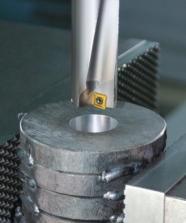
Indexable drills create excellent surface quality because of the insert's complex chip geometry and substrate qualities.
Using this formula you can calculate that a ½-in.-13 UNC thread requires a hole size of 0.466 to 0.469 in. Often custom-sized drills are needed to get the best tool life out of roll form taps as the hole size range is very small.
Hole size and condition can cause many problems with tapping, which are too often wrongly blamed on a tool. With a little education and better preparation, you can achieve increased tool life, reduced costs, and overall success when thread tapping.
Photos courtesy of Komet of America.


Keep up to date with the latest news, events, and technology for all things metal from our pair of monthly magazines written specifically for Canadian manufacturers!
Start Your Free Subscription
Easily access valuable industry resources now with full access to the digital edition of Canadian Metalworking.

Easily access valuable industry resources now with full access to the digital edition of Canadian Fabricating & Welding.


