


Secrets of Selecting the Right CMM
Due diligence and preparation pave the way to success
Selecting a coordinate measuring machine means getting to know a system’s measuring range, accuracy, and software.
It is no mystery that process control and quality assurance in today’s manufacturing operations increasingly depend on the characteristics and performance of coordinate measuring machines (CMMs).
In the past 40 years, CMMs have largely replaced conventional methods of inspection that had gauges and fixtures. These systems have reduced the time and manpower required in quality control operations. Moreover, many measurement operations traditionally reserved for the quality lab have been moved closer to the point of manufacture, further reducing the inspection bottleneck.
Not only do CMMs provide the ability to inspect parts with standard geometrical dimensions, for example, planes, lines, points, circles, and cylinders, but also parts with special features such as gears, camshafts, and airfoil shapes. Prior to the advent of CMMs, each of these special inspections required a single-purpose measuring device.
Product quality and process yield depend on more than just the quality of the machine tool used for manufacturing. They also rely on the accuracy and repeatability of measuring and inspection devices. A low-cost, low-performance machining center in combination with a high-precision CMM can still guarantee product quality because only parts within the tolerance can pass the CMM’s inspection (although the yield may be unacceptably low).
Conversely, an expensive, highquality machining center in combination with a low-cost, low-accuracy measuring device cannot guarantee quality products. A certain percentage of out-of-tolerance parts will always pass the low-accuracy CMM inspection. Likewise, a certain percentage of parts within the tolerance range will be rejected. Consequently, the selection of the right CMM is a critical decision. Following are the main criteria to consider.
Measuring Range
The first important selection criterion is determining the minimum required measuring range of the CMM. This range usually depends on the dimensions of the part to be measured, but it is often more complex than that. For example, if the configuration of the part and the inspection routine require the use of probe extensions and fixtures, the actual minimum required measuring range could be considerably larger than the workpiece’s dimensions.
As a very rough guideline to properly sizing your CMM, consider choosing a machine with X, Y, and Z measuring ranges that are at least twice the width, length, and height of the largest part you intend to measure. However, this rule of thumb is no substitute for thinking through your part holding and measurement strategy in order to determine the correct CMM size.
Accuracy
The second selection criterion is the minimum required CMM accuracy.
One standard for acceptance and verification tests for CMMs utilized for measuring linear dimensions (distances, diameters, position tolerances) is described in ISO 10360-2. Per the standard, a set of five certified lengths are measured three times in nine different positions and directions, yielding a total of 135 measurements (see Figure 1). All of the resulting measurements must be within the manifold defined by the error formula E = A + B • L / 1,000, prescribed by the manufacturer (see Figure 2), where E is the maximum permissible error in microns, L is the measurement length in millimeters, and A and B are constants in microns.
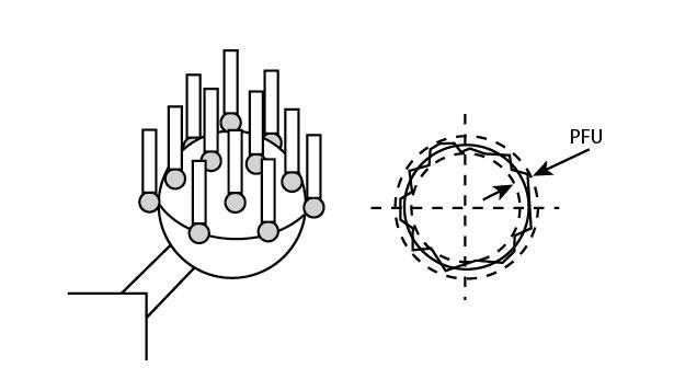
Form measurements (free-form tolerances, straightness, flatness, roundness, and cylindricity) made in single-point mode are described in ISO 10360-5. PFU, the volumetric probing error, is determined by measuring a precision sphere with certified form and diameter using 25 equally spaced points. PFU is the resulting radial form of the sphere (see Figure 3). The result is reported in micrometers (μm), and all 25 points must be used in the calculation.
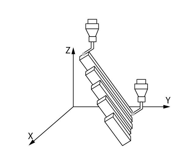
Figure 1
Similarly, for form measurements made in multipoint scanning mode, we refer to ISO 10360-4. THP, the volumetric scanning probing error, is determined by scanning a precision sphere using four defined lines. THP is the range of all radii—the form of the sphere.
These tests are very specific both in definition and execution. It is important to remember that a CMM’s specified maximum permissible error under actual operating conditions can be larger than stated on the manufacturer’s data sheet because of the use of probe extensions, long or slender styli, rotary tables, revolving probe heads, temperature changes, and airborne contaminants in the shop.
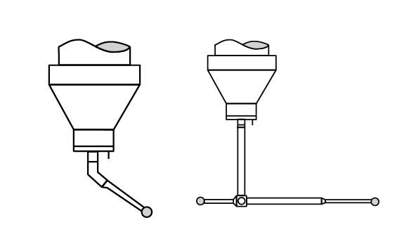
For example, performance specifications are generally specified using one stylus fixed directly in the probe head with no extensions and no rotation. However, the measurement of most workpieces requires complex probe configurations for which E is not specified by the manufacturer. A workpiece might require the combination of several cranked styli, extensions, rotation of the probe head, and perhaps a probe change during the course of the inspection program (see Figure 4).
Because of these differences, a generally accepted practice is to apply a ratio of specified maximum permissible error to tolerance when calculating a required CMM specification. This ratio may vary widely depending on the previously mentioned factors, the complexity of the measurement task, and the process itself. Typical ratios are from 1-to-3 to 1-to-20, with 1-to-5 and 1-to-10 being the most common. In order to maintain a 1-to-5 ratio of uncertainty to part tolerance, the CMM data sheet specification should be five times more accurate than the tolerance being inspected.
Feature Measurement
On almost all workpieces, CMMs must inspect three groups of features: diameters and distances, position tolerances, and form tolerances. An analysis of the required uncertainty must be performed for each group.
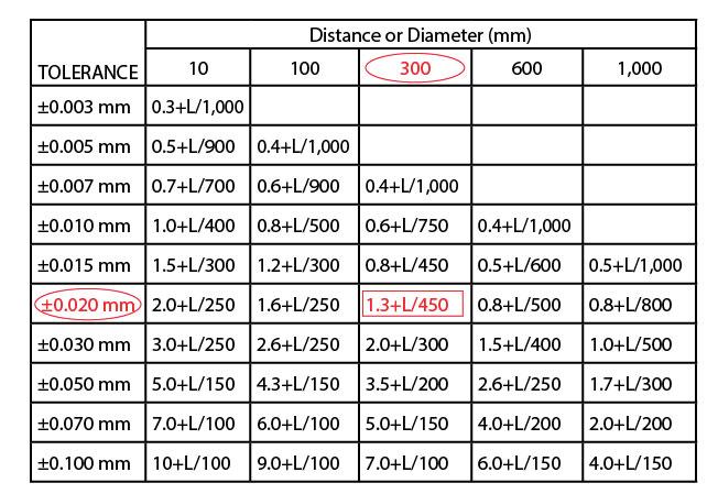
For diameter and distance tolerances, refer to the part drawing and locate the diameter for distances with the tightest tolerances. Because of the length dependency of volumetric uncertainty, a larger tolerance on a very long feature may present more difficulty than a very tight tolerance on a small feature. Figure 5 illustrates how to calculate the required machine volumetric length measurement uncertainty.
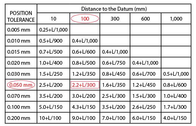
Since position tolerances usually define a tolerance diameter, only the radius is used to determine the deviation from the nominal center. Figure 6 illustrates the method used to calculate the required machine uncertainty.
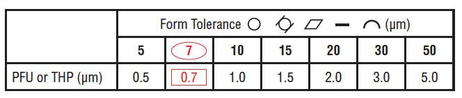
Form tolerances include callouts for roundness, flatness, straightness, cylindricity, and profile form. Figure 7 illustrates the calculation of machine measurement uncertainty for form tolerances.
Temperature, Vibration, Software
The uncertainty of every CMM depends to a great extent on environmental conditions. Consequently, CMM manufacturers usually specify the temperature range, temperature variation per hour, temperature variation per day, and temperature variation per meter within, which determine how a particular CMM achieves its performance specifications. These variables must be considered when selecting a CMM.
In addition, the level of floor vibration also must be considered to optimize the performance of the CMM. Most manufacturers supply the maximum vibration that the machine can withstand and still meet stated specifications. Optional active and passive vibration-dampening systems also can be added, which allow the machine to be installed in less-than friendly environments and still perform to the published specs. A complete seismic vibration study should be performed at the installation site if you believe vibration is an issue.
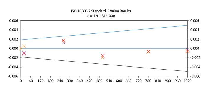
Figure 2
All CMM manufacturers provide software for basic measuring routines. Some also provide specialized software for parts with more complex geometries, such as bevel gears, impellers, screw compressors, and hob cutters. It is important to understand the complexity of the measuring routine needed to inspect your parts, which will affect the selection of a software package that will perform the necessary measurement tasks.
Throughput requirements also should be taken into account. The more parts a CMM inspects per day, the lower the inspection cost per part. Acceleration and the number of probing points per minute are the factors that determine overall throughput. Throughput also can be increased by special fixturing arrangements, such as pallet inspection of parts.
It is no secret that investing in the right CMM can change the playing field. Selecting the CMM most appropriate for your current applications, as well as those in the not-sodistant future, requires forethought and research. Due diligence and preparation can help ensure a smooth buying process.
subscribe now


Keep up to date with the latest news, events, and technology for all things metal from our pair of monthly magazines written specifically for Canadian manufacturers!
Start Your Free Subscription- Stay connected from anywhere

Easily access valuable industry resources now with full access to the digital edition of Canadian Metalworking.

Easily access valuable industry resources now with full access to the digital edition of Canadian Fabricating & Welding.
- Trending Articles