


Ballbar Testing 101
Device can detect backlash, stick-slips, axis reversal spikes
Canadian Industrial Machinery (CIM) asked Philip Smith, technical sales manager for Renishaw Canada, to explain the function of ballbars.
CIM: What is a ballbar?
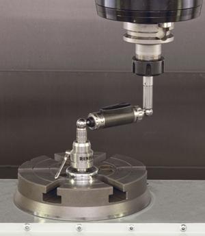
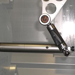
Smith: A ballbar monitors machine tool spindle movement as its follows a programmed circular path (circular interpolation G02 and G03) and compares the machine path to that of an imaginary perfect circle. It consists of a telescopic bar with precision sphere and a kinematic magnetic cup joint located at either end, enabling the ballbar to be repeatably loaded onto the machine. Deviation from the nominal interpolation is measured by a high-accuracy linear sensor within the ballbar.
One end of the ballbar mounts via a magnetic cup onto the machine table, while the ball at the other end attaches to a magnetic cup in the machine’s spindle. These mountings create a three-point kinematic location.
CIM: How does it work?
Smith: It’s a pretty simple concept, really. The machine does a circular interpolation around a fixed point, which is usually on the machine table, and the telescoping ballbar measures any deviation between that fixed point and the spindle.
The heart of the ballbar is a highly accurate (1-µm) optical linear scale with very high resolution (0.1 µ). As the ballbar’s length changes due to slight machine inaccuracies, the optical scale measures what are hoped to be tiny linear displacement changes. This streaming linear displacement data is transmitted back to a computer, which is running the ballbar software.
After the test is complete, the software compiles this data and then calculates 22 machine criteria. For instance, we can look at backlash, squareness, and machine positional capability.
CIM: What kind of area can be measured?
Smith: A typical ballbar test may sweep a 150-mm radius, but tests in the range of 50 mm to more than 600 mm are possible, although rare.
Different lengths may be used to increase sensitivity to particular errors. For example, a longer length may be used to increase sensitivity to geometry errors such as imperfect squareness, whereas a very small radius may be used to highlight dynamic errors such as servo mismatch.
CIM: How are large machine beds measured?
Smith: The ballbar establishes the machine performance characteristics within the machine’s operational area being tested. For a small or medium-sized machine, we usually can obtain sufficient information by swinging a 150-mm- or even a 300-mm-long ballbar, if axis travel allows. Once we get into much larger machines, a number of 300-mm long ballbar tests must be made strategically placed within the machine’s operational area. The software has been designed to enable multiple tests to be performed in different positions on the same machine.
CIM: What are the challenges in measuring larger areas?
Smith: Probably time. Continually having to move and relocate the ballbar to cover the whole machine is quite time-consuming and, frankly, probably unnecessary as a great deal of machine performance data can be established from just a couple of tests at different points on the machine.
CIM: How are very small machines measured?
Smith: A small circle kit is offered to enable the system to be used when interpolating radii as small as 50 mm.
CIM: What about lathes?
Smith: Accessories are available to enable the ballbar to be mounted between the spindle and turret on lathes and vertical turning lathes (VTLs). Frankly, lathes tend to be a little more tricky than HMCs or VMCs mainly because of limited space within the machine and their ability or inability to travel over center.
CIM: How long does a test take?
Smith: Ballbar tests typically take only 10 to 15 minutes and can be performed in just the XY plane; if more detailed machine information is required, we can undertake a dome test in XZ and YZ arcs. Using the software, we can then stitch together these three tests (XY, ZY, and ZX) and establish a theoretical volumetric machine capability.
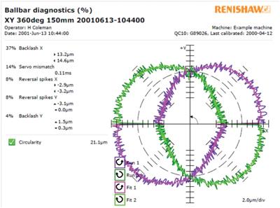
After the ballbar is installed, the machine is programmed to drive its spindle in a circular (interpolated) path that has a radius equal to the length of the ballbar. The ballbar tracks spindle movement to 0.0001 mm and then prioritizes machine errors based on the measured (the interpolated variation) values. It converts the ballbar data into an error-exaggerating polar plot of the machine’s true movement.
An experienced user can identify every error in the machine from this plot; however, for the less experienced operator, sophisticated algorithms in the ballbar software produce a comprehensive diagnostic report that enumerates 22 different dynamic and geometric error values and then ranks them in order of percentage of total error.
It’s immediately clear if the machine has, for instance, any squareness problems. The overall positioning capability (true position) of the machine also is calculated. Reports also may be produced in accordance with ISO, ASME, or JIS standards.
CIM: How can a plot be used over time to better understand the machine?
Smith: Actually, the plot itself can’t, but the software has a rather neat feature that enables all machine data to be viewed graphically, against time. We call this our “machine history” function. This means that any trends can be established and extrapolated if required.
Using this technique it is possible to plan machine maintenance downtime and also ensure any spare parts are ordered well ahead of time. Let’s say that a shop notices a backlash trend in a machine. This is a linear trend, and hence it’s possible to establish an approximate point in the future when the machine will not be capable of making parts.
CIM: What are the benefits for a manufacturer?
Smith: The ballbar takes the guesswork out of determining a machine tool’s capabilities, allowing users to establish a performance level quickly, before the machine cuts chips and makes bad parts. Determining a machine tool’s capabilities before implementing in-process part inspection greatly reduces the potential for component scrap and machine downtime when searching for error sources.
CIM: What specific problems can a ballbar detect?
Smith: The ballbar can see almost every motion-affecting error that exists in the axes. These errors include backlash, reversal spikes, lateral play, cyclic error, servo mismatch, scaling errors, and geometry errors such as imperfect squareness and straightness. It will even measure the actual machine feedrate.
Early error detection with the ballbar permits optimum efficiency in scheduling maintenance and repairs. Ballbar testing is included in a number of standards for machine tool accuracy testing, including ASME B5.54 and ISO 230.
In addition to isolating errors, the ballbar also allows process optimization. For example, users can determine what feedrate delivers the best accuracy for a specific cutting procedure -- such as contouring -- through dynamic checking of the machine tool as it is driven at different feedrates.
CIM: When should a test be performed?
Smith: A ballbar test can be performed at any time; however, realistically, no more than weekly is probably necessary. A machine should be checked every six months at minimum if everything is running well.
In the case of a new machine, once it’s been commissioned, it’s probably a good idea to get the machine supplier to provide an initial ballbar plot that can be used as a machine benchmark.
In the event of a collision, if a ballbar test has been done previously, it can quickly be established if any damage has been done.
CIM: What is the latest technology in ballbar testing?
Smith: Renishaw’s newest ballbar, the QC20-W, has seen two real improvements over its predecessor, the QC10. First, it communicates wirelessly using Bluetooth® technology to a laptop running the diagnostic software.
Over the last few years, issues relating to machine guarding and interlocking meant trying to use a ballbar with a cable became more and more problematic. Now, with the advent of the wireless version, we can easily and quickly test even the most heavily guarded and impregnable machines.
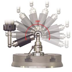
Second, we have made some small design changes to the way in which the ballbar is mounted to its pivots. This means that when it’s running a dome test, the ballbar swings through 220 degrees. When it’s used in conjunction with our latest volumetric software, theoretical machine volumetric capability can be established.
subscribe now


Keep up to date with the latest news, events, and technology for all things metal from our pair of monthly magazines written specifically for Canadian manufacturers!
Start Your Free Subscription- Stay connected from anywhere

Easily access valuable industry resources now with full access to the digital edition of Canadian Metalworking.

Easily access valuable industry resources now with full access to the digital edition of Canadian Fabricating & Welding.
- Trending Articles